CompTIA A+ Core 2 Question G-79

A user has an external hard drive which they forget to unplug before booting their machine. Each time this happens, an error shows on the screen which states “Boot sector missing reboot to try again.” Which of the following would be the BEST way to resolve this?

A. Change BIOS options to remove floppy drive from the boot order
B. Change BIOS options to remove USB device from the boot order
C. Change BIOS options to remove CD drive from the boot order
D. Set the SATA setting in BIOS to AHCI from IDE
CompTIA A+ Question J-47

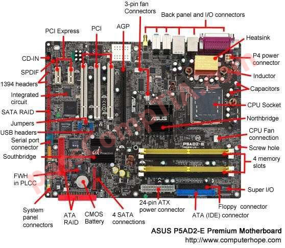
Which of the following is the correct connector for an internal floppy drive?

A. 50-pin SCSI
B. 40-pin ribbon
C. 34-pin ribbon
D. 4-pin SATA

Correct Answer: C

CompTIA A+ Question A-63

A technician needs to install an appropriate PSU into a new machine. The technician needs available power for a floppy drive, two older IDE hard disks, a single SATA hard disk, and an IDE optical drive. How many unique power connectors will the PSU need to accommodate the listed devices?

A. 2
B. 3
C. 4
D. 5

Correct Answer: B

Explanation:
Three power connectors are enough to power a floppy drive, old IDE hard disk a single SATA disk and an optical drive. This is possible because a single connector has multiple connectors that can be plugged into these devices.

CompTIA A+ Question A-58

When installing a floppy drive data cable, it is important for a technician to ensure which of the following? (Select TWO).

A. Availability of compatible power connectors
B. Adequate hard drive capacity
C. Correct CPU clock speeds
D. Correct Master/Slave jumper settings
E. Proper orientation of the data cable

Correct Answer: AE

CompTIA A+ Simulation 3

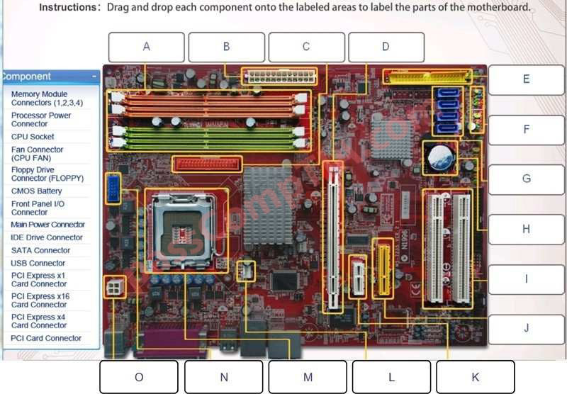
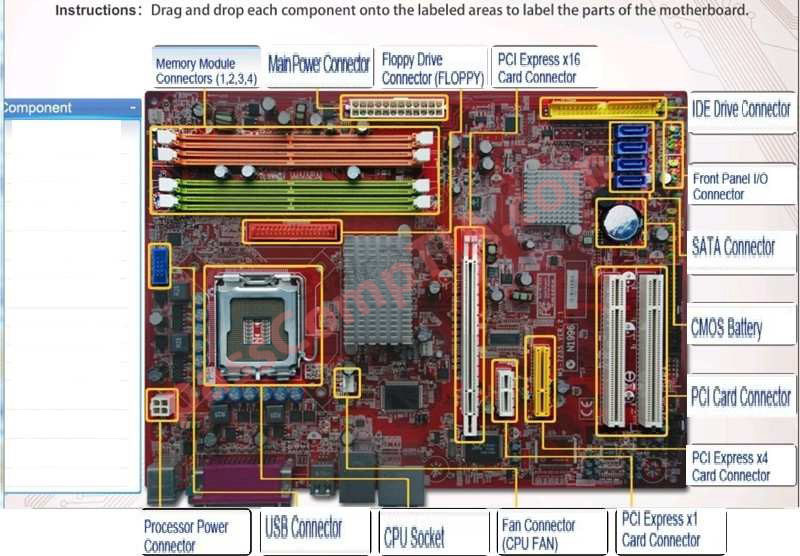
Instructions: Drag and drop each component onto the labeled areas to label the parts of the motherboard.

Correct Answer:
A – Memory Module Connectors (1, 2, 3, 4)
B – Main Power Connector
C – Floppy drive connector (FLOPPY)
D – PCI Express x16 card connector
E – IDE Drive Connector
F – Front Panel I/O Connector
G – SATA Connector
H – CMOS Battery
I – PCI Card Connector
J – PCI Express x4 connector
K – PCI Express x1 card connector
L – Fan Connector (CPU FAN)
M – CPU Socket
N – USB Connector
O – Processor Power Connector


Explanation:

Refer to http://www.build-your-own-computer.net/motherboard-diagram.html